Please leave us a message

Low-voltage automatic regulating device User Manual

Share
1、Product introduction

In the low-voltage power distribution system, the voltage on the user side is too low due to the long power supply line in some station areas. In order to solve the above problems, our company has developed and designed a low-voltage automatic voltage regulator.

The low-voltage automatic voltage regulator is mainly composed of a main control module, a voltage regulation module, and a monitoring module. The device can monitor the incoming line voltage in real time. When the incoming line voltage exceeds the normal range, the device will automatically adjust the voltage with load through its own voltage regulating module to keep the output voltage within the acceptable range.

The device has the characteristics of small size, low power consumption, automatic adjustment of power supply line voltage, convenient installation and maintenance, and high reliability.

2、Product model and its meaning

The LSVR low-voltage automatic voltage regulator has five gears, including two gears for boosting, two gears for stepping down, and one gear for bypassing. The device is mainly composed of adjustable transformer, circuit breaker, current transformer, compensation capacitor and so on. Its pressure regulation mode is mainly automatic pressure regulation.

The product model description is shown in Figure 1: the current main capacity is 10kVA, 20kVA, 30kVA, 60kVA, 90kVA and the size of the chassis is also different according to the difference between single-phase and three-phase.

3、Conditions of Use:

— Suitable for 220/380V, 50Hz grid system; other systems need to communicate in advance.

— Do not place it in places where the relative air humidity is greater than 90% for a long time;

–The altitude is not higher than 2000m;

— Ambient temperature -10℃~+50℃;

–There is no serious vibration and violent turbulence at the installation site, and no flammable, explosive and corrosive media that seriously affect the insulation of the voltage regulator.

— Cannot run in parallel.

4、 Product advantages and features

— It can solve the power supply voltage drop caused by long power supply lines and large load changes

–Using advanced voltage and tracking technology, it is suitable for areas with unstable grid frequency, large voltage fluctuations and frequent fluctuations.

–With input side voltage over/low voltage protection; output side voltage over/low voltage protection; output overload protection and other functions.

–The three-phase output is controlled separately and adjusted independently.

–With automatic bypass control system for safe operation.

–No surge current, no harmonic distortion, no mechanical wear, and maintenance-free during use.

5、Specifications
Model LSVR-**/**-**
Rated capacity/kVA 10、20、30、40 (single phase)

30、60、90、120(three-phase)

Special capacity can be customized

Adjust gear 4/5 gears
AC input AC input Rated voltage 380V (line voltage)、220V (single phase)
Voltage regulation range 305V~420V、176V~242V(conventional voltage regulation range)

Special voltage regulation range can be customized

Frequency 50HZ
AC Output Rated voltage 380V(line voltage)、220V(single phase)
Voltage regulation accuracy ±5%
Output waveform The output waveform has no distortion and no harmonic increment
Adjustment method Three-phase separate adjustment, output voltage unbalance is less than 2%.
Protection Overload Real-time monitoring of load current, after 3 minutes of continuous overload, switch to bypass output
Short circuit When a short circuit fault occurs, the molded case circuit breaker cuts off the output instantaneously
Equipment failure When the voltage regulator itself fails, it will automatically switch to the bypass output
Undervoltage hold When the input voltage is lower than 176V, the voltage regulator continues to maintain the boost output
Display voltage/current LED display
Working status Stabilized voltage status/mains status/fault status
Instantaneous overload capacity 200%/10S
Noise (1m away from the machine) <45dB at 1m <45dB at 1m
Cooling method Self-cooling
environment Temperature -10ºC~45ºC
Relative humidity 35%~95% (non-condensing state)
6、 Installation Diagram

After the installation point of the low-voltage automatic voltage regulator is determined, install our company’s matching device bracket and diagonal brace at a distance of 3 meters from the ground on the pole. After the installation is firm, hoist the device in place. The bracket is fixed firmly. After the device is fixed in place, the grounding device is installed and connected firmly with the housing. The installation diagram is shown in the figure below:
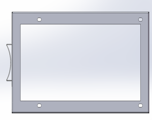
Figure 2 Mounting the bas
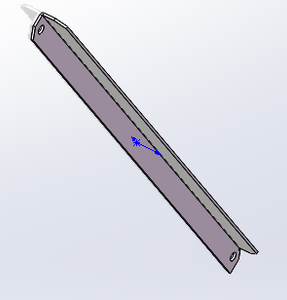
Figure 3 Installing the angle iron
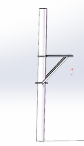
Figure 4 Schematic Diagram of Installation Combination
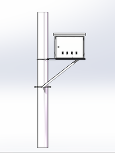
Figure 5 Installation Diagram

FAQ
Get A Free Quote
TOP
Global Cooperation
Our professional team will reply you as soon as possible.
Home Product About Contact